
SUNTES AP-2403 Power Supply Box for E-Boosters and Electromagnetic Brakes
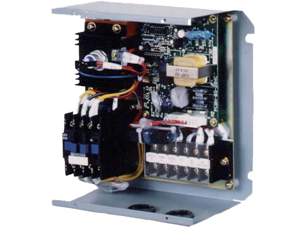
Product Overview
The SUNTES AP-2403 is the power supply box specified for the E-Booster range and the listed electromagnetic disc-brake range. It provides separate output conditions for actuator pull-in and subsequent energized holding, allowing the electrical supply to be matched to the actuator sequence.
The published application families are DB-41**EF and DB-41**EFT E-Boosters, and DB-40**EF electromagnetic brakes. The wildcard designations identify product families; the exact connected models and number of actuators still need to be checked when defining a control system.
Operation and Performance
Supply voltage is AC180–240 V at 50/60 Hz. The listed pull-in output is DC150–210 V, and holding output is DC20–30 V. The maximum-current entry is 17 A under the stated condition of two DB-415* units connected, at pull-in with an AC240 V supply. That condition is part of the rating and should be retained when comparing controller capacity.
The box is rated at 1,800 cycles/h and has a mass of 4.0 kg. Main terminal screws are M4 and ALARM terminal screws are M3. The controller cycling figure does not replace the individual duty limit of a connected E-Booster or brake; the complete system must satisfy both sets of requirements.
Detailed Specifications
| Technical Specifications | |
|---|---|
| Supply voltage (V) | AC180–240 50/60Hz |
| Output voltage at pull-in (V) | DC150–210 |
| Output voltage at holding (V) | DC20–30 |
| Maximum current (A) | 17 (DB-415* with two units connected, at pull-in with AC240 V supply) |
| Duty rating | 1800cycles/h |
| Terminal screw size | Main terminal block: M4 ALARM terminal block: M3 |
| Applicable equipment | All E-booster models: : DB-41**EF, DB-41**EFT All electromagnetic brake models: : DB-40**EF |
| Mass (kg) | 4.0 |
Model Configuration and Compatibility
The E-Booster specification separately lists its own pull-in and holding-voltage ranges, holding power and required supply capacity. For example, the actuator holding-voltage range may extend to DC31 V while this controller table specifies a DC20–30 V holding output. Retain the individual component ratings rather than rewriting them as one common value.
Use the dimensional drawing and block diagram for the actual AP-2403 installation. Confirm terminal identification, the connected actuator type and quantity, supply voltage and the required control sequence against the matching equipment documentation.
Drawings and Performance References
Use the dimensional and performance references for the exact assembly. Lettered dimensions correspond to the drawing; a dash or blank in a specification is retained as stated and is not an additional rating.


Selection and Installation Considerations
Prepare a connected-load list before selecting the box. Include every actuator model, the number that can pull in simultaneously, the required cycling rate and the individual energized-holding duty. Compare the worst intended operating condition with the stated controller and actuator ratings.
Allow installation space for wiring, access to the terminal blocks and servicing. Review the control and alarm connections as part of the complete brake system. No enclosure protection class, additional output functions or compatibility beyond the stated families is assumed here.
Ordering Information
Specify AP-2403, supply voltage and frequency, connected E-Booster or brake models and quantities, simultaneous operating requirements, cycling duty and the installation drawing. Include the existing wiring diagram when replacing a controller.