
SUNTES Custom Hydraulic Power Units — Brake-System Design and Application Examples
Product Overview
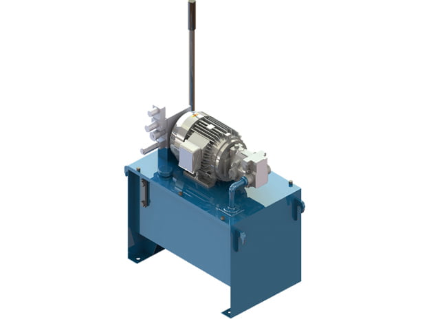
SUNTES designs and supplies hydraulic power units to suit the operating requirements of its brake installations. The motor, pump and reservoir are selected around the actual brake duty, rather than treated as one fixed combination for every application.
This is a project-specific hydraulic-unit offering. The product information does not assign a single standard ordering model, so the published examples below are reference installations and are not presented as interchangeable stock models.
Operation and Performance
Three application examples illustrate the range of configured systems. An elevator hoisting-machine installation uses a 0.75 kW motor, 13.7 MPa maximum pressure, 1.2 L/min delivery and a 20 L tank. A container-crane luffing installation uses a 0.75 kW motor, 14.0 MPa maximum pressure, 1.5 L/min delivery and a 30 L tank.
The ladle-crane main-hoist example uses a 3.7 kW motor, 16.7 MPa maximum pressure, 9.4 L/min delivery and a 100 L tank. These are complete application examples: motor power, flow, pressure and reservoir volume belong to the stated installation and should not be mixed to imply a different standard unit.
Detailed Specifications
| Published Application Examples — Project-Specific Configurations | ||||
|---|---|---|---|---|
| Application | Motor (kW) | Maximum pressure (MPa) | Flow (L/min) | Tank (L) |
| Elevator hoisting machine | 0.75 | 13.7 | 1.2 | 20 |
| Container-crane luffing equipment | 0.75 | 14.0 | 1.5 | 30 |
| Ladle-crane main hoist | 3.7 | 16.7 | 9.4 | 100 |
Model Configuration and Compatibility
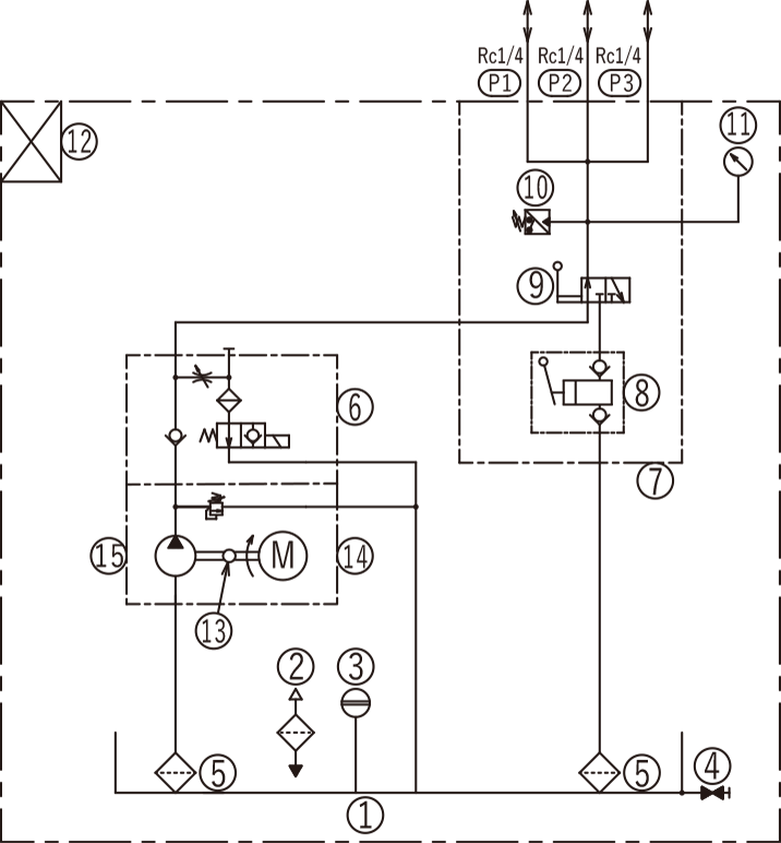
The reference hydraulic circuit identifies a reservoir, filler/air breather, oil-level gauge, ball valves, suction strainer, solenoid valve, manifold, hand pump, pressure switch, pressure gauge, terminal box, coupling, motor and gear pump. The supplied circuit is a reference arrangement; the final equipment configuration must be agreed for the project.
The configuration process needs enough information to select the motor, pump and tank capacity. SUNTES requests the required operating conditions for this purpose. A clear brake-circuit description is therefore more useful than requesting a unit solely by the horsepower of an existing motor.
Drawings and Performance References
Use the dimensional and performance references for the exact assembly. Lettered dimensions correspond to the drawing; a dash or blank in a specification is retained as stated and is not an additional rating.
Selection and Installation Considerations
Define the brake models and quantity, required hydraulic pressure, fluid volume per operation, application and release times, operating frequency, supply voltage and fluid specification. Add the ambient conditions, available installation envelope, pipe-run information and required control sequence. These are engineering inputs for reviewing a configured system, not additional published performance ratings.
For an existing installation, include the hydraulic and electrical drawings, present motor/pump nameplates, tank volume and the operating issue or replacement objective. The proposed unit can then be checked against the actual system requirements and connection points.
Ordering Information
Enquire as a SUNTES custom hydraulic power-unit project and provide the complete operating requirements. Confirm the resulting configuration, drawings and assigned project or unit identification before procurement; no standard model code is invented for this offering.