
SUNTES DB-3277A Air-to-Hydraulic Booster
Product Overview
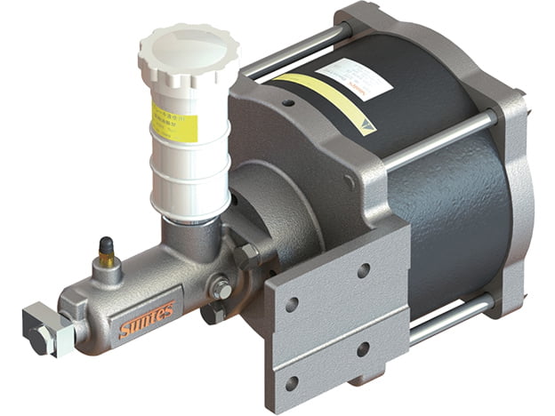
The SUNTES DB-3277A converts a pneumatic input into hydraulic pressure for a compatible hydraulic disc-brake circuit. It combines a pressure-intensifying mechanism with a master cylinder, allowing an air control signal to operate the hydraulic side of the brake installation.
This is an air-actuated configuration. SUNTES describes the air-booster family as a way to control hydraulic disc brakes through air supply on/off operation. The hydraulic output and the required brake-fluid displacement both need to match the connected brake.
Operation and Performance
The nominal pressure intensification ratio is 22:1. Specified air pressure is 0.05–0.45 MPa, and the displaced hydraulic-fluid volume is 28 cm³. The assembly mass is 30 kg. These figures describe different selection limits: the ratio concerns pressure multiplication, while displacement describes the finite volume available to move the brake pistons.
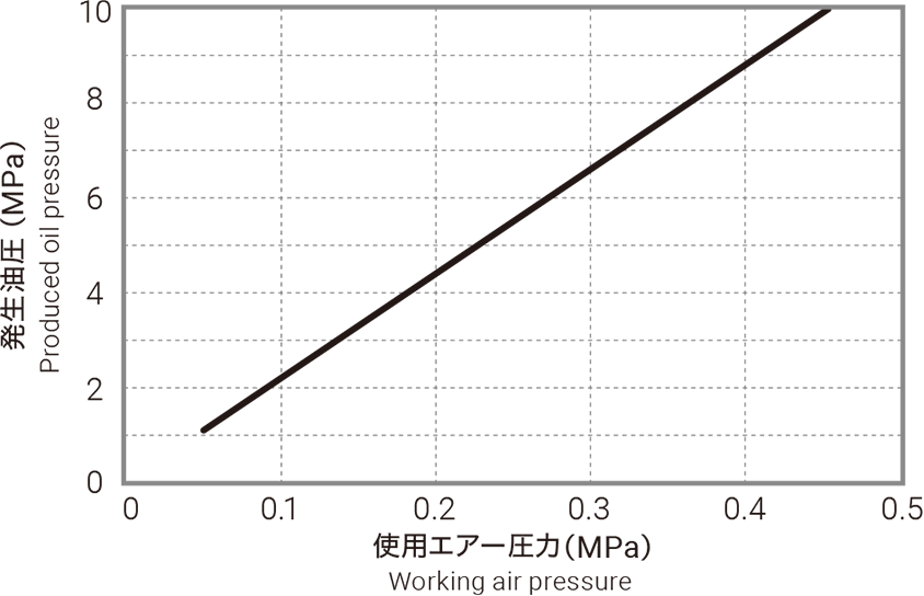
The listed master-cylinder configuration is DB-2207MS-01. Select by both the required hydraulic pressure and the total fluid volume needed per application, including the actual number of connected calipers and their operating stroke. A higher ratio alone does not establish whether a booster has enough displacement for the circuit. Use the supplied pressure characteristic for the selected model rather than treating the nominal ratio as a complete output-pressure rating.
Detailed Specifications
| Technical Specifications | |
|---|---|
| Master cylinder model | DB-2207MS-01 |
| Operating fluid | Brake fluid (DOT3 equivalent) |
| Discharge volume (cm3) | 28 |
| Operating air pressure (MPa) | 0.05–0.45※ |
| Pressure intensification ratio | 22 |
| Mass (kg) | 30 |
Model Configuration and Compatibility
The listed configuration uses DOT3-equivalent brake fluid with master cylinder DB-2207MS-01. A mineral-oil version is not specified in this product table.
The minimum air-pressure figure is a reference value. SUNTES notes that individual sliding resistance can change the minimum pressure required for operation. Preserve the complete model suffix when replacing an existing unit, because fluid specification and master-cylinder configuration are part of the selection.
Drawings and Performance References
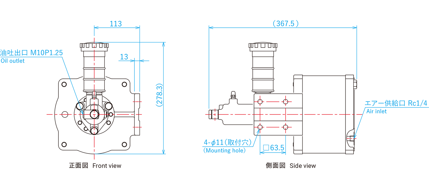
Use the dimensional and performance references for the exact assembly. Lettered dimensions correspond to the drawing; a dash or blank in a specification is retained as stated and is not an additional rating.
Selection and Installation Considerations
For integration, establish the required brake torque first, then determine the corresponding caliper pressure and fluid volume. Compare the result with the booster specification and the pressure characteristic. The downstream hydraulic components must be selected for the actual operating pressure; the maximum permitted air input is specific to this model.
Check mounting clearances, master-cylinder access, air and hydraulic connections, and the route of the brake-fluid piping against the dimensional drawing. As a general hydraulic-system commissioning step, verify correct filling, removal of trapped air and complete apply/release movement with the selected brake. Confirm the installation procedure against the matching equipment instructions.
Ordering Information
Specify the complete booster model and suffix, master-cylinder code, required fluid, available air pressure, required hydraulic pressure, fluid demand per operation, connected brake models and quantity. Include the existing drawing or nameplate when ordering a replacement.