
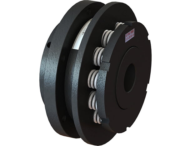
SUNTES TX15D, TX20D, TX30D, TX40D and TX50D Automatic-Reset Torque Releasers. These units interrupt power transmission when the torque in the drive system exceeds the selected setting. Choosing the correct size, spring variant and mechanical interface helps limit the effects of sudden overloads on the connected machinery. The full model suffix identifies the setting configuration and must be retained in an order.
Configuration and installation interface
The D configuration uses a flange interface. The dimensional table specifies the mounting bolt pitch-circle diameter and bolt size separately, in addition to the locating diameters and their tolerances. Compatible roller-chain sprockets require the matching D-type machining dimensions.
Automatic-reset operating sequence
During normal operation, spring force holds the steel balls in the hub-boss pockets and torque passes through the balls to the flange. When an overload drives the balls out along the pocket ramps, torque transmission is interrupted. The action ring moves axially toward the adjust ring; that displacement can be detected by a limit switch or proximity switch. After the cause of overload has been removed, rotation of either the input or output brings the balls back to the prescribed pocket position, once per revolution, where the springs automatically reset the mechanism.
Torque setting and characteristic curves
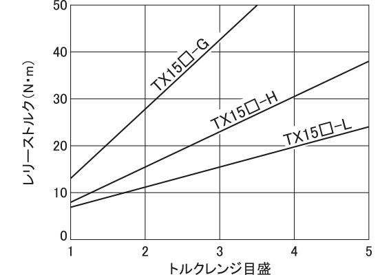
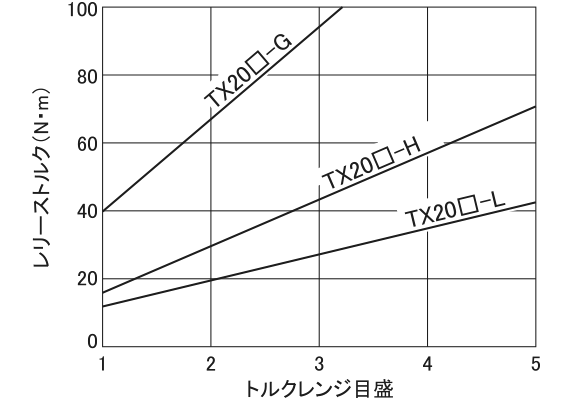
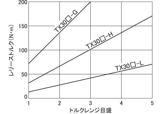
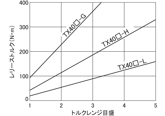
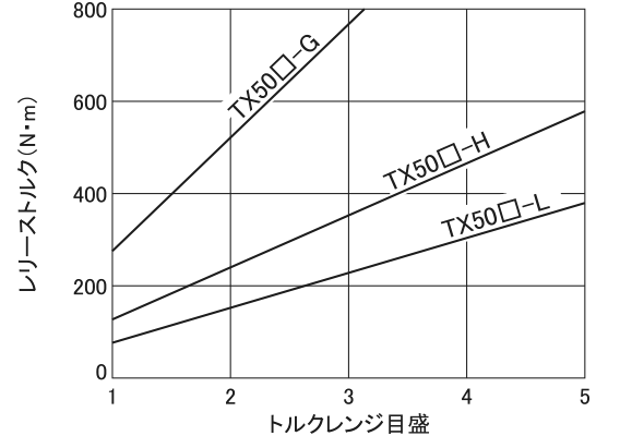
The L, H and G variants have distinct torque-setting ranges and spring combinations. The specification table gives spring color and quantity, maximum speed, moment of inertia and product mass. Torque can be varied in proportion to the number of springs, with a stated minimum of three springs. Use the characteristic curve for the appropriate size when reviewing a setting. Changing spring count requires the correct configuration and adjustment procedure; the top of a torque range is not a universal recommended operating setting.
Selection and ordering
Specify the exact type, size, L/H/G variant, required release torque, actual shaft speed and shaft-bore arrangement. Include normal running torque, startup conditions, the driven-machine duty and the mounting details. Check overload-detection travel and allow access for adjustment and reset. Where a value spans several rows, it applies to the associated grouped variants. Fit tolerances, pilot bores and screw callouts are retained in the data below. Confirm the current drawing and application suitability before machining mating components.
Dimensions and specifications
Use the lettered dimensions with the corresponding drawing. Torque is stated in N·m, speed in min⁻¹, and mass in kg where indicated. Fit tolerances, drawing symbols, grouped rows and blank entries are retained. A blank entry is not zero.
Dimensions
| Model | A | B | C | D | E | φF | φG | φH | φJ | Mounting bolts | |
|---|---|---|---|---|---|---|---|---|---|---|---|
| K P.C.D. | L bolt size | ||||||||||
| TX15D-L・H・G | 47 | 10 | 6.0 | 4 | 13.7 | 69 | 50 +0 -0.025 | 56 | 96 | 60 | 6-M5 |
| TX20D-L・H・G | 53 | 11 | 8.3 | 4 | 15.1 | 88 | 65 +0 -0.030 | 68 | 108 | 75 | 6-M6 |
| TX30D-L・H・G | 65 | 13 | 10.5 | 6 | 20.0 | 113 | 85 +0 -0.035 | 84 | 124 | 100 | 6-M6 |
| TX40D-L・H・G | 75 | 15 | 13.2 | 6 | 20.3 | 134 | 105 +0 -0.035 | 108 | 148 | 120 | 6-M8 |
| TX50D-L・H・G | 90 | 20 | 15.8 | 8 | 24.8 | 168 | 130 +0 -0.040 | 134 | 174 | 150 | 6-M10 |
Performance specifications
| Model | Torque setting range (N·m) | Spring color × quantity | Maximum speed (min⁻¹) | Moment of inertia (kg·m²) | Product mass (kg) |
|---|---|---|---|---|---|
| TX15D-L | 7~24 | White × 10 | 900 | 0.58×10⁻³ | 1.0 |
| TX15D-H | 8~38 | Red × 5 | |||
| TX15D-G | 13~50 | Red × 10 | |||
| TX20D-L | 12~43 | White × 12 | 750 | 1.3×10⁻³ | 1.5 |
| TX20D-H | 16~70 | Red × 6 | |||
| TX20D-G | 40~100 | Red × 12 | |||
| TX30D-L | 14~72 | White × 12 | 600 | 3.7×10⁻³ | 3.0 |
| TX30D-H | 33~170 | Red × 6 | |||
| TX30D-G | 72~200 | Red × 12 | |||
| TX40D-L | 20~160 | White × 12 | 450 | 9.6×10⁻³ | 5.0 |
| TX40D-H | 43~330 | Red × 6 | |||
| TX40D-G | 97~400 | Red × 12 | |||
| TX50D-L | 79~390 | White × 12 | 400 | 26.4×10⁻³ | 10.0 |
| TX50D-H | 130~580 | Red × 6 | |||
| TX50D-G | 280~800 | Red × 12 |
Torque-releaser shaft interface
| Model | Maximum shaft bore (φmm) | Standard shaft bore (φmm) | Pilot bore (φmm) | Set screws | Axial travel on overload (mm) |
|---|---|---|---|---|---|
| TX15D-L・H・G | 15 | 15H7×5Js | 9 | 2-M4 | 1.5 |
| TX20D-L・H・G | 20 | 20H7×6Js9 | 12 | 2-M4 | 1.9 |
| TX30D-L・H・G | 30 | 30H7×8Js9 | 19 | 2-M4 | 2.6 |
| TX40D-L・H・G | 40 | 40H7×12Js9 | 24 | 2-M5 | 2.9 |
| TX50D-L・H・G | 50 | 50H7×14Js9 | 34 | 2-M8 | 3.8 |


Confirm the latest dimensional drawing and specifications for the selected configuration before manufacture or installation.