
SUNTES hydraulic piping connectors provide hose nipples, nipples, bushings and two-, three- and four-way connections for brake piping. The range covers several thread and pipe-end systems, making the complete part number essential when selecting an adapter or branch connector. The dimensional tables below retain every listed variant and its corresponding thread designations.
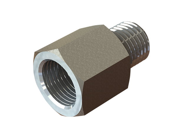
Thread and dimensional identification
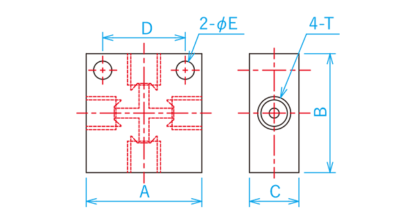
T1 through T4 identify the connections shown in each dimensional drawing. A through E refer to the corresponding drawing dimensions. DM denotes the M10 P1.25 double-flare interface, CU the 3/8-24UNF convex interface, and CM the M10 P1.0 convex interface. Check both thread and seating profile against the mating pipe or equipment. Similar thread diameters do not establish compatibility.
Hose nipples — DB-0302-01 and DB-0302-02
The hose nipple range includes an R1/4 version and an M16 P1.5 version. The asterisk on DB-0302-02 identifies a straight hose-attachment section. Match the T1 thread and the A, B and C dimensions to the installation drawing.
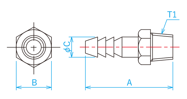
| Part number | T1 | A | B | C |
|---|---|---|---|---|
| DB-0302-01 | R1/4 | 40 | 14 | 9.5 |
| DB-0302-02※ | M16 P1.5 | 36 | 26 | 10 |
Nipples — DB-0306-01, DB-0306-02, DB-0306-A03 and DB-0306-04
All four listed nipples have a G1/8 T1 connection. Their T2 ends differ: R1/8, DM (M10 P1.25), CU (3/8-24UNF), and CM (M10 P1.0). Their A dimensions also differ, so selection should cover both interface and available space.
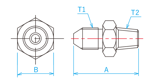
| Part number | T1 | T2 | A | B |
|---|---|---|---|---|
| DB-0306-01 | G1/8 | R1/8 | 29 | 14 |
| DB-0306-02 | G1/8 | DM(M10 P1.25) | 32 | 14 |
| DB-0306-A03 | G1/8 | CU(3/8-24UNF) | 37.5 | 14 |
| DB-0306-04 | G1/8 | CM(M10 P1.0) | 28 | 14 |
Bushings — DB-0309 series
The bushing range includes eight part numbers with different combinations of CU, DM, CM, Rc, R and metric threads. DB-0309-01 is specified for the DB-2204T teacher master cylinder. DB-0309-A01 has a different A dimension and must be identified by its full code.
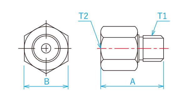
| Part number | T1 | T2 | A | B |
|---|---|---|---|---|
| DB-0309-01 | CU(3/8-24UNF) | Rc1/8 | 23 | 14 |
| DB-0309-A01 | CU(3/8-24UNF) | Rc1/8 | 31 | 14 |
| DB-0309-02 | DM(M10 P1.25) | Rc1/8 | 26 | 14 |
| DB-0309-04 | CM(M10 P1.0) | Rc1/8 | 23 | 14 |
| DB-0309-05 | M14 P1.5 | DM(M10 P1.25) | 29 | 19 |
| DB-0309-06 | R1/4 | CU(3/8-24UNF) | 28 | 19 |
| DB-0309-07 | DM(M10 P1.25) | CU(3/8-24UNF) | 32 | 14 |
| DB-0309-08 | R1/8 | CU(3/8-24UNF) | 30 | 14 |
Two-way connectors — DB-0301 and DB-0303
Two straight versions provide matching DM or CU connections. The square DB-0303-01 combines CU and Rc1/8 connections. The table retains merged cells where the same connection applies to more than one port.
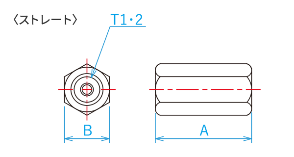
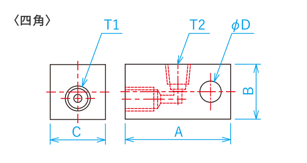
| Part number | T1 | T2 | A | B | C | D | Shape |
|---|---|---|---|---|---|---|---|
| DB-0301-01 | DM(M10 P1.25) | 30 | 14 | - | - | Straight | |
| DB-0301-02 | CU(3/8-24UNF) | 30 | 14 | - | - | Straight | |
| DB-0303-01 | CU(3/8-24UNF) | Rc1/8 | 42 | 22 | 22 | 8.5 | Square |
Three-way connectors — DB-0300 series
DB-0300-01 is a square three-way connector with DM connections. DB-0300-03 is hexagonal with Rc1/8 connections. The square DB-0300-05 combines CU connections at T1 and T2 with PF1/4 at T3. Keep the original PF designation when specifying this part.
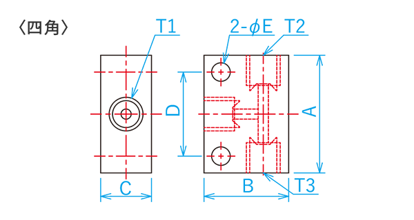
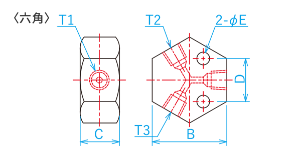
| Part number | T1 | T2 | T3 | A | B | C | D | E | Shape |
|---|---|---|---|---|---|---|---|---|---|
| DB-0300-01 | DM(M10 P1.25) | 35 | 25 | 15 | 25 | 5.5 | Square | ||
| DB-0300-03 | Rc1/8 | - | 38 | 20 | 22 | 6.5 | Hexagonal | ||
| DB-0300-05 | CU(3/8-24UNF) | PF1/4 | 50 | 30 | 20 | 40 | 5.5 | Square | |
Four-way connector — DB-0305-01
DB-0305-01 provides four DM (M10 P1.25) connections. Its A through E dimensions are shown in the table and referenced in the drawing. Check the port layout and mounting dimensions together when arranging a multi-branch hydraulic line.
| Part number | T1 | T2 | T3 | T4 | A | B | C | D | E |
|---|---|---|---|---|---|---|---|---|---|
| DB-0305-01 | DM(M10 P1.25) | 35 | 36 | 15 | 25 | 5.5 | |||
Selection information
Select the connector function first, then compare every port designation with the intended mating component. Check the envelope and mounting dimensions against the drawing before finalizing the arrangement. Preserve suffixes such as A03 and A01 in purchase documentation because these identify distinct variants. Dimensions and specifications may change with product improvement.