
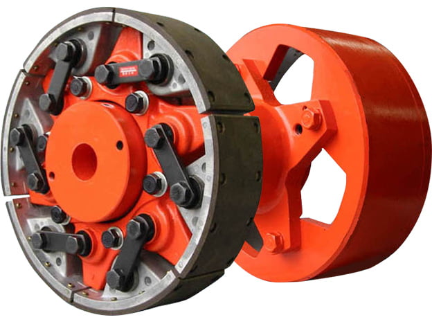
SUNTES C-Series centrifugal clutches connect an engine or other driving machine to a driven load through centrifugal force and friction. The basic clutch arrangement supports smoother starting and helps protect the shaft system when an overload occurs. The series covers twelve listed models, from C-53 to C-4510, with several shoe configurations and engagement-speed settings.
Progressive engagement and power transmission
At rest, the driving unit and drum are separated, so the clutch does not transmit power through frictional contact. As the driving speed increases, centrifugal force moves the shoes outward against the drum. Torque is progressively transferred while the clutch slips during acceleration. At the intended rated operating speed, the clutch is designed to transmit power without continuing slip. This operating sequence allows the driving machine to accelerate before taking the full driven load; the actual starting behaviour depends on the selected shoe arrangement and the connected machinery.
Construction and service identification
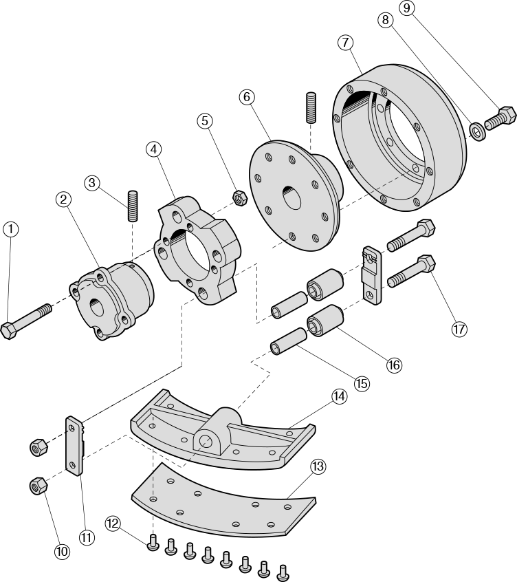
The assembly includes a hub boss, shoe supports, shoes, friction linings, link plates, sleeves, rubber bushes, and the drum rim and flange. Springs, mounting bolts, rivets and locking hardware complete the mechanism. The exploded view is useful when identifying the assembly and discussing service parts. Match the complete clutch model, shoe specification and installation arrangement before ordering replacement components; dimensional similarity alone does not establish interchangeability.
Typical equipment applications
The C-Series is intended for engine-driven drainage pumps, fire pumps, refrigerated-truck compressors and hydraulic pumps used in construction machinery. In these applications, the clutch can help reduce the immediate load imposed on the engine during starting. Application selection should account for engine idle speed, normal running speed, driven-machine starting torque, rotating inertia, acceleration time and the frequency of starts. A clutch selected only by shaft diameter may not provide the required engagement behaviour.
Understanding engagement speed and selection
The specification table distinguishes L, H and G shoes. Their engagement figures are speeds in rpm, not maximum permissible running speeds or torque capacities. For example, C-53 lists 1,240 rpm with L shoes, 990 rpm with H shoes and 740 rpm with G shoes. Dashes identify entries for which no value is listed. The standard shaft bores shown for the smaller units include the H7 tolerance designation; larger models show a dash and require confirmation of the actual shaft arrangement.

Models, dimensions and technical data
Dimensions are in millimetres unless otherwise specified. Lettered dimensions refer to the corresponding drawings; diameter symbols and drawing references are retained.
C-Series dimensions (mm)
| Model | A | B | C | D | E | F | G | H | J | K | L | M | N |
|---|---|---|---|---|---|---|---|---|---|---|---|---|---|
| C-53 ① | 38 | 45 | 10 | 161 | 15 | 35 | 60 | 15 | 35 | 80 | 107 | 27 | 70 |
| C-73 ① | 54 | 50 | 7 | 213 | 20 | 50 | 85 | 20 | 50 | 88 | 120 | 32 | 85 |
| C-93 ① | 67 | 65 | 7 | 270 | 20 | 70 | 115 | 25 | 70 | 102 | 149 | 47 | 130 |
| C-123 ② | 89 | 90 | 7 | 340 | 40 | 80 | 135 | 30 | 80 | 130 | 200 | 70 | 143 |
| C-136 ② | 100 | 90 | 6 | 367 | 40 | 85 | 160 | 30 | 85 | 130 | 200 | 70 | 143 |
| C-156 ③ | 115 | 127 | 6 | 414 | 45 | 115 | 146 | 45 | 115 | 148 | 248 | 94 | 178 |
| C-186 ③ | 150 | 152 | 8 | 494 | 65 | 127 | 196 | 64 | 150 | 176 | 310 | 110 | 230 |
| C-218 ③ | 152 | 152 | 7 | 576 | 70 | 150 | 210 | 64 | 150 | 172 | 311 | 112 | 230 |
| C-248 ③ | 172 | 153 | 6 | 656 | 70 | 165 | 235 | 70 | 165 | 238 | 331 | 93 | 254 |
| C-308 ③ | 203 | 203 | 13 | 817 | 70 | 175 | 288 | 75 | 200 | 248 | 419 | 133 | 305 |
| C-368 ③ | 254 | 254 | 12 | 984 | 100 | 200 | 292 | 100 | 200 | 283 | 520 | 184 | 350 |
| C-4510 ③ | 254 | 280 | 12 | 1,245 | 100 | 225 | 405 | 100 | 225 | 318 | 546 | 228 | 349 |
Standard bore, engagement speed and mass
| Model | Unit standard shaft bore | Engagement speed (rpm) | Product mass (kg) | |||
|---|---|---|---|---|---|---|
| L shoe | H shoe | G shoe | Unit | Drum | ||
| C-53 | 35φH7 | 1,240 | 990 | 740 | 1.97 | 4.5 |
| C-73 | 45φH7 | 1,120 | 900 | 610 | 5.27 | 9.1 |
| C-93 | 55φH7 | 900 | 720 | 520 | 9.46 | 18.0 |
| C-123 | 65φH7 | 780 | 590 | - | 18.54 | 28.5 |
| C-136 | 80φH7 | 660 | 380 | - | 28.58 | 32.5 |
| C-156 | - | 620 | 450 | 370 | 46.56 | 54.7 |
| C-186 | - | 460 | 330 | 280 | 82.4 | 87.0 |
| C-218 | - | 420 | 300 | 240 | 92.3 | 116.0 |
| C-248 | - | 350 | 270 | 220 | 156.9 | 158.4 |
| C-308 | - | 240 | 170 | 160 | 291.0 | 287.6 |
| C-368 | - | 240 | 190 | - | 322.0 | 667.0 |
| C-4510 | - | 160 | 120 | 100 | 640.0 | 1,090.0 |
Engagement-speed data use the MAX Set for C-53 through C-123 and the MID Set for C-136 through C-4510. Versions with a higher engagement speed are available for applications requiring idling operation; confirm the required setting before selection. Circled numbers in the dimension table identify drawing groups. Confirm the latest dimensional drawing, allowable operating conditions and complete application rating before manufacture or installation.