
SUNTES DB-2173 / DB-2173D Hand-Lever Hydraulic Brake Units
Product Overview
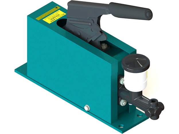
The SUNTES DB-2173 hand-lever unit is a manually operated hydraulic pressure generator. Pulling the lever produces hydraulic pressure for the connected brake circuit, providing an operator-controlled actuation point without a foot-pedal assembly.
Two configurations are listed: DB-2173 and DB-2173D. Their displaced volume is the same, but master-cylinder reference, tank-hose information and mass differ. The complete D suffix should therefore be retained in the ordering description.
Operation and Performance
Both versions provide 5 cm³ hydraulic displacement. DB-2173 uses master-cylinder reference DB-2203M and has a mass of 5.9 kg; DB-2173D uses DB-2203MD and has a mass of 6.4 kg.
The tank-hose entry is a dash for DB-2173 and 5 m for DB-2173D. The fluid specification lists DOT3-equivalent brake fluid or ISO VG32-equivalent mineral oil. Confirm the actual configured fluid version and the connected brake requirements when selecting the complete assembly.
Detailed Specifications
| Technical Specifications | ||
|---|---|---|
| Model | DB-2173 | DB-2173D |
| Master cylinder model | DB-2203M | DB-2203MD |
| Operating fluid | Brake fluid (DOT3 equivalent) or Mineral oil (ISO VG32 equivalent) | |
| Discharge volume (cm3) | 5 | |
| Tank hose length (m) | - | 5 |
| Mass (kg) | 5.9 | 6.4 |
Model Configuration and Compatibility
SUNTES revised the unit shape in July 2024 following a hand-lever change. Compare the current lever and mounting envelope with the existing assembly when replacing an earlier unit. A matching base code alone does not establish that the old and current outlines are identical.
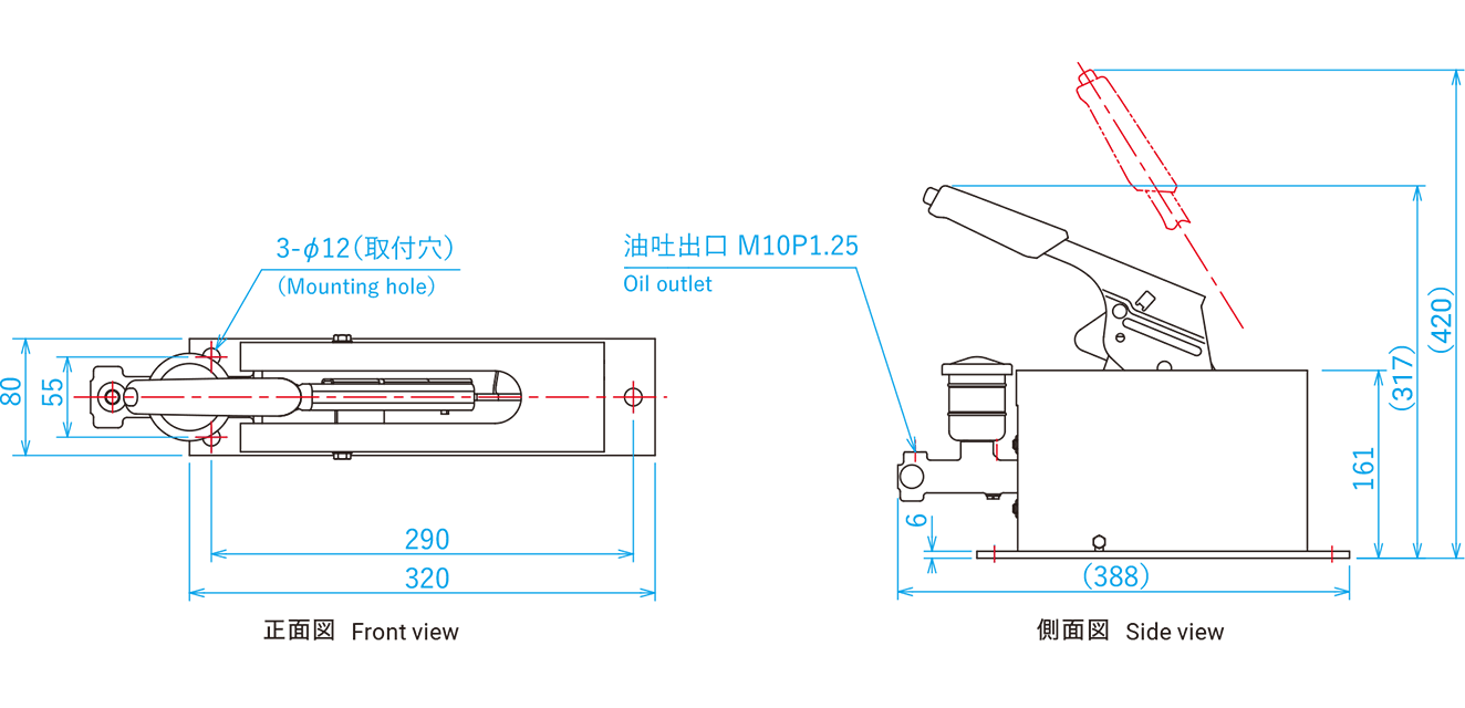
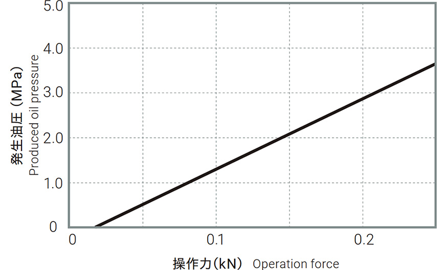
The generated-pressure characteristic and dimensional drawing belong to this hand-lever assembly. Use those references to assess the operating point and installation; a 5 cm³ displacement figure alone does not define the hydraulic pressure or resulting brake torque.
Drawings and Performance References
Use the dimensional and performance references for the exact assembly. Lettered dimensions correspond to the drawing; a dash or blank in a specification is retained as stated and is not an additional rating.
Selection and Installation Considerations
Determine the hydraulic pressure and fluid volume required by the brake before selecting the lever unit. Review the number of connected calipers, operating stroke, control sequence and the pressure required for the intended braking duty.
Check lever position, operator reach, available lever travel, mounting clearances, access for servicing and the route of the tank hose where fitted. Confirm the installed brake, master cylinder and fluid specification as one compatible circuit, then use the matching filling, bleeding and commissioning instructions.
Ordering Information
Specify DB-2173 or DB-2173D, required fluid, connected brake models and quantity, required pressure and displacement, hose arrangement, quantity and installation drawing. Include a nameplate photo and outline of the installed unit, especially for equipment using the earlier lever shape.