
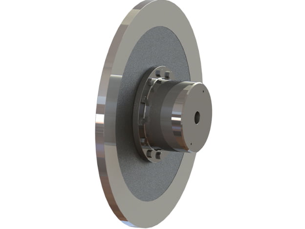
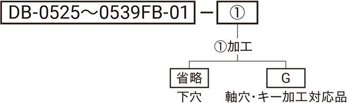
SUNTES flange-boss brake discs combine a flange mounting arrangement with a boss interface. The eight listed models are DB-0525FB, DB-0526FB, DB-0527FB, DB-0535FB, DB-0536FB, DB-0537FB, DB-0538FB and DB-0539FB. Retain the FB suffix when selecting or ordering the assembly.
Disc sizes and mounting geometry
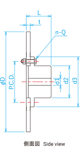
The DB-0525FB through DB-0527FB group uses thickness t of 20, with D dimensions of 500, 600 and 700. DB-0535FB through DB-0539FB use t at 38, with D values from 500 through 900. The drawing also specifies the d1 pilot and maximum bore, d2, d3, overall L, pitch-circle diameter and n-Q fastener callout. A shared outer diameter does not make a 20-thick and a 38-thick model interchangeable.
Model-specific performance data
Maximum rotational speeds range from 1,450 to 2,600 min⁻¹ across the listed models. For example, DB-0525FB and DB-0535FB both list 2,600 min⁻¹, but their inertia and mass differ: 1.1 kg·m² and 51 kg for DB-0525FB, compared with 2.0 kg·m² and 76 kg for DB-0535FB. The larger DB-0539FB lists 20.12 kg·m² and 276 kg. All inertia and mass values are stated at the pilot-bore dimensions.
Drawing and shaft-interface review
Use the separate pilot-bore and maximum-bore entries under d1. Check the flange bolt circle and fastener pattern together with the boss interface and disc offset. The complete row is required to prepare mating components; similarity in one diameter or bolt size is insufficient. Confirm the brake clearance and final bore arrangement for the actual installation.
Ordering and manufacture
Provide the full FB model code, brake identification, operating speed, braking duty, finished bore requirement and flange interface. Include any installation-space and handling constraints associated with the selected mass. For customer-manufactured discs, request a design review before production. The dimensional and speed data do not establish a universal braking torque or thermal duty. Confirm the current drawing and approved application configuration before machining or ordering.
Complete technical data
Dimensions and mounting interface
| Model | D | t | d1 | d2 | d3 | L | P.C.D. | n-Q | |
|---|---|---|---|---|---|---|---|---|---|
| Pilot bore | Max. | ||||||||
| DB-0525FB | 500 | 20 | 35 | 95 | 160 | 250 | 125 | 205 | 8-M16 |
| DB-0526FB | 600 | 20 | 35 | 115 | 190 | 280 | 145 | 240 | 10-M16 |
| DB-0527FB | 700 | 20 | 50 | 130 | 215 | 305 | 165 | 260 | 12-M16 |
| DB-0535FB | 500 | 38 | 35 | 95 | 160 | 250 | 143 | 205 | 8-M16 |
| DB-0536FB | 600 | 38 | 35 | 115 | 190 | 280 | 163 | 240 | 10-M16 |
| DB-0537FB | 700 | 38 | 50 | 130 | 215 | 305 | 183 | 260 | 12-M16 |
| DB-0538FB | 800 | 38 | 50 | 150 | 250 | 340 | 208 | 295 | 12-M16 |
| DB-0539FB | 900 | 38 | 50 | 170 | 280 | 380 | 228 | 330 | 12-M18 |
Speed, inertia and mass
| Model | DB-0525FB | DB-0526FB | DB-0527FB | DB-0535FB | DB-0536FB | DB-0537FB | DB-0538FB | DB-0539FB |
|---|---|---|---|---|---|---|---|---|
| Maximum rotational speed (min⁻¹) | 2600 | 2200 | 1900 | 2600 | 2200 | 1900 | 1600 | 1450 |
| Moment of inertia (kg·m²) | 1.1 | 2.2 | 4.0 | 2.0 | 3.94 | 7.27 | 12.48 | 20.12 |
| Mass (kg) | 51 | 75 | 103 | 76 | 111 | 152 | 210 | 276 |
Inertia and mass values are stated at the pilot-bore dimensions.
Dimensions and specifications may change as products are improved. Confirm the selected configuration and latest drawing before manufacture or installation.