
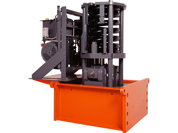
SUNTES RC-Series rail clampers directly grip the rail to restrain crane movement caused by typhoons or sudden strong winds. Intended equipment includes large travelling cranes such as unloaders and container cranes. The standard range consists of RC-1013, RC-1018, RC-1026, RC-1038, RC-1050 and RC-1075, with model-specific clamping forces and installation dimensions.
Integrated hydraulic arrangement
The clamper incorporates a hydraulic power unit in an integrated assembly to simplify installation. Its internal arrangement accommodates rail-alignment variations, and the functional components are designed with durability in mind. Various rail types can be accommodated, subject to confirmation of the actual rail profile and selected configuration. The complete installation must match the crane structure, rail geometry and available space.
Six clamping-force ratings
The listed rail clamping forces are 127 kN for RC-1013, 176 kN for RC-1018, 254 kN for RC-1026, 372 kN for RC-1038, 490 kN for RC-1050 and 735 kN for RC-1075. The specification table also retains the corresponding kgf figures. These are clamping-force ratings; they must not be substituted directly for a longitudinal holding-force requirement. Selection requires the intended resistance to crane movement and the actual rail/contact conditions to be reviewed together.
Model-specific dimensions
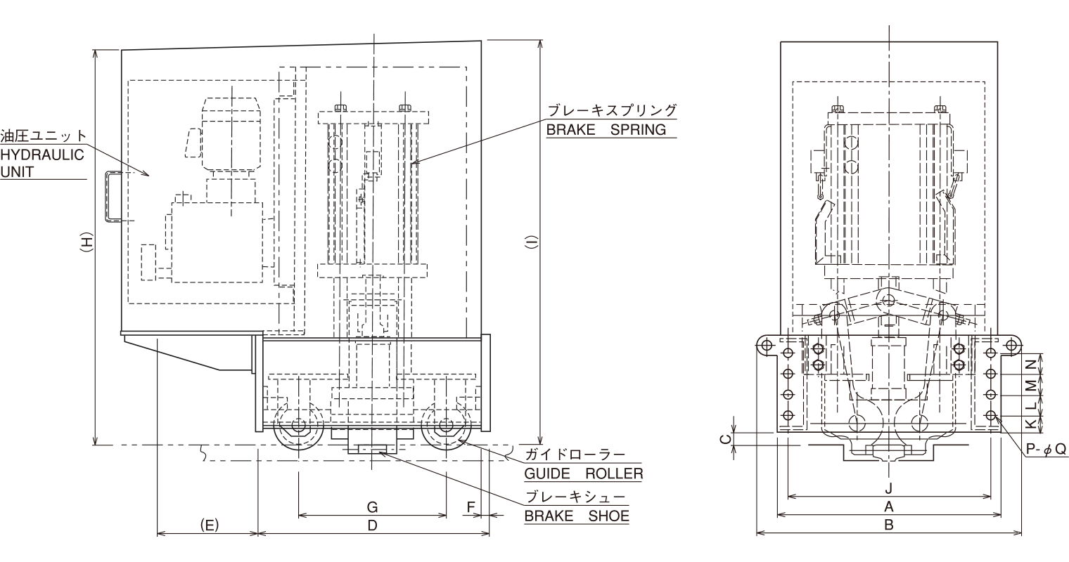
The dimensional table includes A through K, the combined L/M/N reference, P and diameter Q. Parenthesized E, H and I references are preserved as shown on the drawing. RC-1013 and RC-1018 share many dimensions but differ in the H and I references. RC-1038 and RC-1050 also have different height-related drawing entries despite sharing several other values. Compare the full model row when checking a replacement or preparing mounting components.
Rail condition and application review
Identify the rail standard, head width, wear condition and alignment before specifying the clamper. The conventional arrangement has a recommended rail-side wear range of 2 mm, as described in the comparison with the long-stroke version. Where increased wear accommodation is needed, review the separate long-stroke configuration rather than assuming that a higher clamping-force standard model provides the same travel. Confirm the installation limits and current dimensional drawing for the selected unit.
Ordering information
Provide the complete RC model, crane application, required restraint duty, rail profile and condition, mounting arrangement and electrical/hydraulic integration requirements. Allow access for inspection and service. The standard dimensional and force tables do not establish a universal release time, motor rating or allowable wind speed. Confirm those application-specific requirements before ordering or manufacturing brackets and mating components.
Dimensions and technical specifications
Lettered dimensions refer to the corresponding drawing. Retain the complete model suffix when selecting an assembly.
Dimensional data
| Model | A | B | C | D | (E) | F | G | (H) | (I) | J | K | L, M, N | P | φQ |
|---|---|---|---|---|---|---|---|---|---|---|---|---|---|---|
| RC-1013 | 700 | 820 | 40 | 730 | 400 | 25 | 460 | 1060 | 1090 | 630 | 55 | 65 | 8 | 26 |
| RC-1018 | 700 | 820 | 40 | 730 | 400 | 25 | 460 | 1200 | 1230 | 630 | 55 | 65 | 8 | 26 |
| RC-1026 | 730 | 850 | 40 | 750 | 400 | 25 | 480 | 1230 | 1260 | 660 | 60 | 70 | 8 | 26 |
| RC-1038 | 780 | 935 | 40 | 800 | 400 | 28 | 520 | 1290 | 1320 | 700 | 80 | 95 | 8 | 33 |
| RC-1050 | 780 | 935 | 40 | 810 | 400 | 28 | 520 | 1360 | 1390 | 700 | 80 | 95 | 8 | 33 |
| RC-1075 | 820 | 975 | 40 | 870 | 400 | 32 | 590 | 1540 | 1570 | 730 | 85 | 95 | 8 | 36 |
Rail clamping force
| Model | Rail clamping force | |
|---|---|---|
| kN | kgf | |
| RC-1013 | 127 | 13000 |
| RC-1018 | 176 | 18000 |
| RC-1026 | 254 | 26000 |
| RC-1038 | 372 | 38000 |
| RC-1050 | 490 | 50000 |
| RC-1075 | 735 | 75000 |
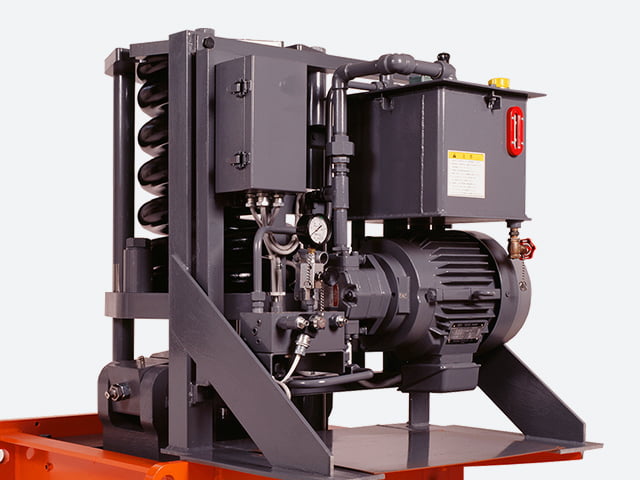
Dimensions and specifications may change as products are improved. Confirm the selected configuration and latest drawing before manufacture or installation.