
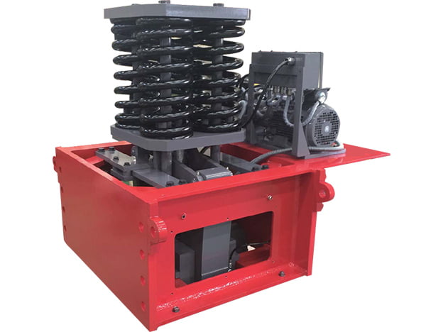
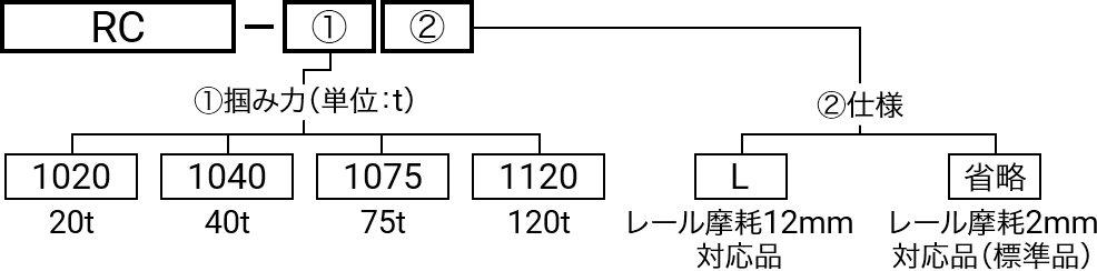
SUNTES long-stroke rail clampers directly grip the rail to restrain large cranes against wind-induced runaway. The range comprises RC-1020L, RC-1040L, RC-1075L and RC-1120L. Their extended travel is designed to maintain the specified clamping force as rail-head width decreases through wear, within the stated conditions.
Rail wear accommodation
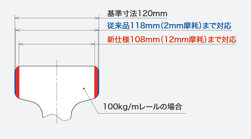
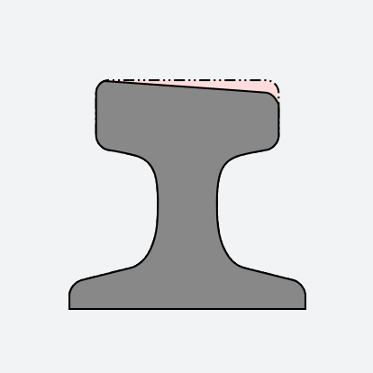
The conventional rail clamper has a recommended rail-side wear range of 2 mm. With new shoes, the long-stroke type can maintain its specified clamping force with up to 12 mm wear relative to the standard rail-head width. The 12 mm figure is conditional on new shoes and should not be read as 12 mm permitted on each side. The separately listed shoe wear allowance is 1 mm per side. Review rail wear and shoe wear together when assessing an installation.
Rail geometry and tracking
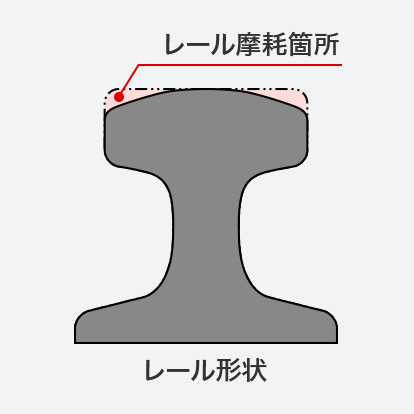
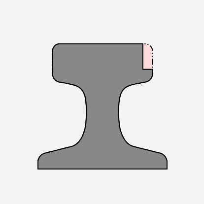
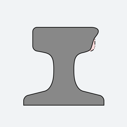
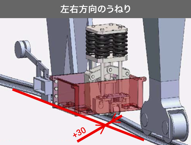
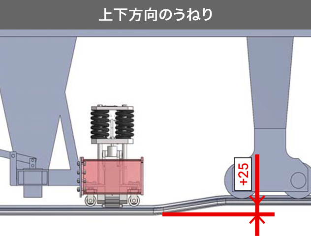
The internal unit follows rail undulation along the travel direction, accommodating lateral variation of ±30 mm and vertical variation of ±25 mm. The design can be adapted to standard rail profiles. However, wear accommodation does not make every deformed rail suitable for clamping. Rails with a rolled-over top edge, a tilted top surface, a step on the side or a bulged side require correction or replacement to restore a clampable profile. The illustrations show the wear example and the rail conditions that need attention.
Clamping force versus holding force
RC-1020L, RC-1040L, RC-1075L and RC-1120L have clamping forces of 196, 392, 735 and 1,176 kN respectively. At the listed coefficient of friction of 0.25, the corresponding runaway holding forces are 98, 196, 368 and 588 kN. These two sets of ratings describe different functions and must remain separate in the crane restraint calculation. The largest clamping-force figure is not the longitudinal holding-force rating.
Hydraulic unit, motion and electrical supply
The hydraulic power unit is integrated for convenient installation; a separately located unit is available as an option. Cylinder diameters range from 105 to 230 mm, and strokes from 115 to 132 mm. Release time is approximately 5 seconds, while clamping time is adjustable with a minimum of approximately 2 seconds. These marked timing values apply to new rails without deformation or wear. Motor power is 1.5, 2.2, 3.7 or 5.5 kW by model, and tank capacity is 5 or 10 L as listed. Motor and control supply options are specified separately in the table.
Monitoring, fluid and coating
Interlock devices include temperature and level switches. The listed working fluid is antiwear hydraulic oil in ISO VG22 or VG32 grades. The coating specification uses an epoxy-resin primer and polyurethane-resin topcoat. Cold-climate, seismic-isolation, special electrical-supply and special-coating configurations are available for review. Specify the actual installation environment and required power supply when requesting the final configuration.
Inspection and selection
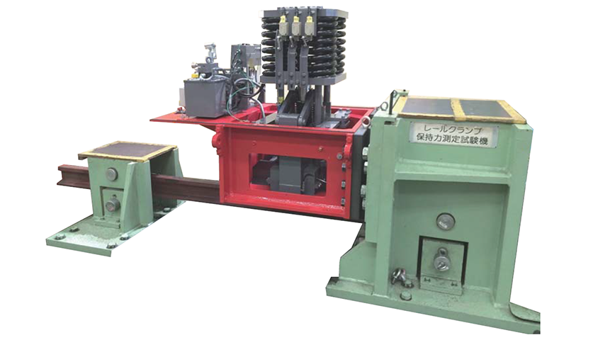
Before shipment, the clamper undergoes a runaway holding-force test. It grips a rail in the test apparatus while load is applied, and the rail is checked for movement. For application selection, provide the complete model, required holding force, rail standard and measured condition, alignment variations, crane mounting details and available utilities. Confirm the current drawing, maintenance criteria and operating sequence before approving the installation.
Dimensions and technical specifications
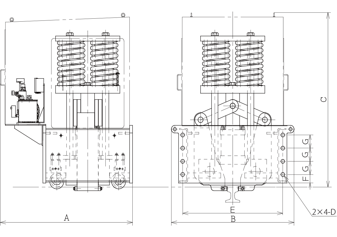
Lettered dimensions refer to the corresponding drawing. Retain the complete model suffix when selecting an assembly.
Dimensional data
| Model | A | B | C | D | E | F | G |
|---|---|---|---|---|---|---|---|
| RC-1020L | 1180 | 935 | 1180 | φ26 | 750 | 55 | 65 |
| RC-1040L | 1220 | 1065 | 1290 | φ33 | 830 | 80 | 95 |
| RC-1075L | 1320 | 1225 | 1450 | φ39 | 980 | 85 | 95 |
| RC-1120L | 1500 | 1335 | 1660 | φ39 | 1090 | 85 | 130 |
Performance, operating conditions and utilities
| Model | RC-1020L | RC-1040L | RC-1075L | RC-1120L |
|---|---|---|---|---|
| Clamping force (kN) | 196 | 392 | 735 | 1,176 |
| Coefficient of friction | 0.25 | |||
| Runaway holding force (kN) | 98 | 196 | 368 | 588 |
| Cylinder diameter (mm) | φ105 | φ145 | φ190 | φ230 |
| Cylinder stroke (mm) | 115 | 116 | 121 | 132 |
| Release time | Approximately 5 s* | |||
| Clamping time | Adjustable (minimum approximately 2 s*) | |||
| Rail-head width wear allowance | Accommodates up to 12 mm wear relative to the standard rail-head width | |||
| Shoe wear allowance | 1 mm per side | |||
| Motor power (kW) | 1.5 | 2.2 | 3.7 | 5.5 |
| Tank capacity (L) | 5 | 5 | 10 | 10 |
| Power supply: motor | AC 200/400 V, 50 Hz, three-phase; AC 200/220/400/440 V, 60 Hz, three-phase | |||
| Power supply: control | AC 100–110 V / AC 200–220 V, 50/60 Hz, single-phase | |||
| Interlock devices | Temperature switch and level switch | |||
| Hydraulic fluid | Antiwear hydraulic oil, ISO VG22 / VG32 | |||
| Coating specification | Primer: epoxy-resin paint; topcoat: polyurethane-resin paint | |||
| Options | Cold-climate specification, seismic-isolation specification, special power supply, special coating and other options | |||
* Marked operating times apply to a new rail without deformation or wear. The 12 mm rail-head wear accommodation is stated with new shoes.
Dimensions and specifications may change as products are improved. Confirm the selected configuration and latest drawing before manufacture or installation.