
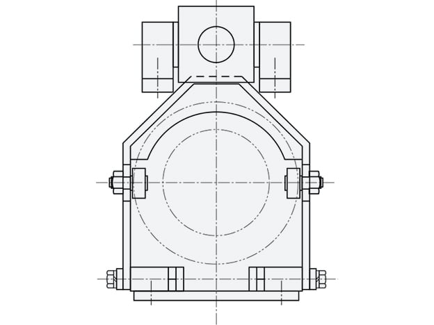
SUNTES ON/OFF shifters are associated with TY-Series torque releasers. The listed dimensional range covers TY30, TY40, TY50, TY65 and TY85. The shifter arrangement and air-cylinder specification must be matched to the actual TY assembly and the available installation space.
Role in the TY installation
TY torque releasers use a manual-reset clutch mechanism. After an overload, the cause must be removed and the correct alignment and reset sequence followed. The shifter is a separate accessory arrangement; its dimensional data do not change the release-torque rating of the torque releaser. Review the required ON/OFF and reset operation for the complete machine before choosing the actuator and control sequence.
Two complementary dimensional tables
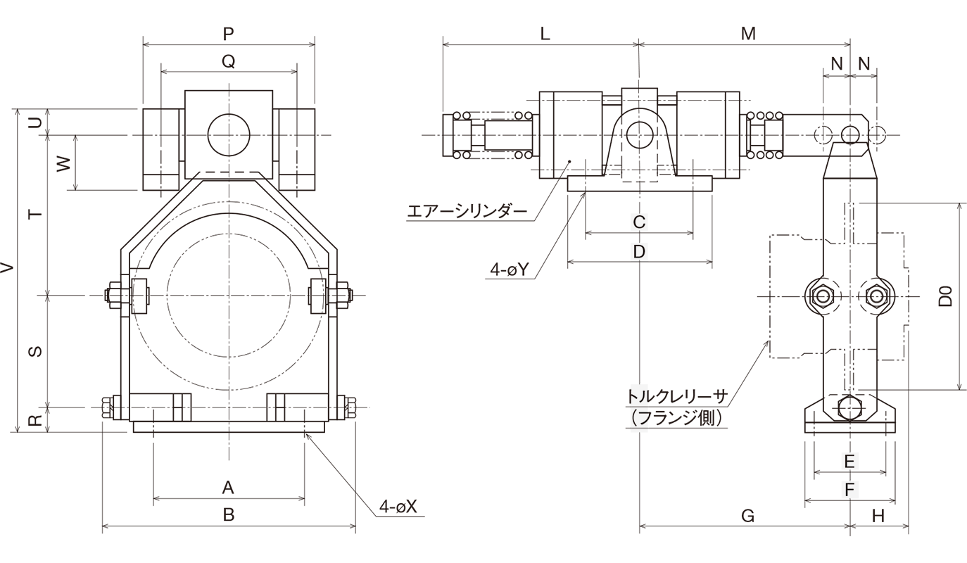
The first table gives dimensions A through H and L through P. The second continues with Q through W, diameters X, Y and D0, and the air-cylinder specification. Both rows for the same TY size are needed to define the arrangement. Do not combine one size's main dimensions with another size's cylinder data. Check every letter against the corresponding drawing, including the support and mounting envelope.
Cylinder specification and layout
The air-cylinder entries are 63 × 30ST for TY30, 80 × 30ST for TY40, 100 × 35ST for TY50, 125 × 45ST for TY65 and 160 × 50ST for TY85. Retain these complete callouts when discussing the arrangement. The table does not provide an operating-air pressure, switching time or control-circuit specification. Confirm those requirements for the selected cylinder and machine installation rather than assuming that dimensions alone establish actuator performance.
Selection and ordering
Provide the full TY releaser model and size, the desired shifter arrangement, mounting constraints and the proposed operating sequence. Review access to the reset mechanism, alignment marks and overload-detection components. Check the current accessory drawing together with the releaser drawing before manufacturing brackets or releasing a purchase order. The complete machine control must determine when shifting and restarting are permitted; use the approved operating procedure for the selected assembly.
Dimensions and specifications
Use the lettered dimensions with the corresponding drawing. Torque is stated in N·m, speed in min⁻¹, and mass in kg where indicated. Fit tolerances, drawing symbols, grouped rows and blank entries are retained. A blank entry is not zero.
Main dimensions
| Model | A | B | C | D | E | F | G | H | L | M | N | P |
|---|---|---|---|---|---|---|---|---|---|---|---|---|
| TY30 | 120 | 189 | 70 | 100 | 55 | 75 | 169 | 45.5 | 124 | 169 | 15 | 150 |
| TY40 | 140 | 219 | 90 | 120 | 65 | 90 | 177 | 46.5 | 147 | 177 | 15 | 192 |
| TY50 | 180 | 266 | 90 | 120 | 80 | 110 | 182 | 56.0 | 152 | 182 | 17.5 | 214 |
| TY65 | 220 | 321 | 105 | 145 | 100 | 130 | 222 | 64.5 | 182 | 222 | 22.5 | 236 |
| TY85 | 290 | 398 | 140 | 185 | 100 | 130 | 246 | 91.0 | 201 | 246 | 25 | 294 |
Additional dimensions and air cylinder
| Model | Q | R | S | T | U | V | W | φX | φY | φD0 | Air cylinder specification (φmm) |
|---|---|---|---|---|---|---|---|---|---|---|---|
| TY30 | 130 | 20 | 90 | 135 | 18 | 263 | 55 | 10 | 11 | 150 | 63 × 30ST |
| TY40 | 166 | 25 | 110 | 165 | 25 | 325 | 75 | 12 | 13.5 | 175 | 80 × 30ST |
| TY50 | 188 | 30 | 130 | 195 | 25 | 380 | 75 | 14 | 13.5 | 210 | 100 × 35ST |
| TY65 | 203 | 35 | 150 | 225 | 32 | 442 | 85 | 14 | 18 | 250 | 125 × 45ST |
| TY85 | 253 | 35 | 190 | 285 | 40 | 550 | 130 | 18 | 22 | 330 | 160 × 50ST |
Confirm the latest dimensional drawing and specifications for the selected configuration before manufacture or installation.