
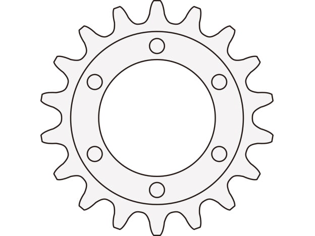
SUNTES roller-chain sprockets for TY-A and TY-D torque releasers must be selected by the complete releaser configuration, chain size and required tooth count. The compatibility matrix below lists the tooth-count ranges that can be fitted for each combination. The machining table then defines the mating interface used to attach the sprocket to the releaser.
Reading the compatibility matrix
Column headings beginning with # identify roller-chain sizes, while T denotes the number of teeth. A range such as 27–46T describes the listed tooth-count interval for that chain and releaser combination. Blank cells mean that no compatible range is listed; they do not indicate zero teeth or unrestricted compatibility. Select the exact model row and chain-size column together before checking the required tooth count.
Configuration-specific machining
The second table must be used with the dimensional drawing. Lettered dimensions, bolt-circle references, hole callouts, fit classes and surface-finish symbols identify different machining requirements. A D-type flange and an A-type interface can require different sprocket geometry even when the nominal releaser size is the same. Preserve the model prefix and suffix throughout drawing preparation and purchasing. The tolerance values shown with H7 fits must be included when checking the locating interface.
Drive integration
Tooth count forms part of the chain-drive ratio and affects the sprocket geometry. Verify the intended chain specification, mating sprocket, available installation space and alignment as part of the drive design. The compatibility table describes available mounting combinations; it does not by itself establish a chain load rating, an allowable machine speed or a torque-release setting. Those requirements must be checked separately for the complete drive.
Ordering and drawing review
Provide the TY releaser type and size, chain number, tooth count and the required mating-interface drawing. State whether a sprocket or a completed releaser assembly is required. Before manufacture, check the full machining row, including locating fits, bolt pattern and finish callouts, against the current drawing. Values marked with ≤ mean the stated maximum. Drawing symbols are retained so that their meaning can be checked in context; they should not be converted into assumed numerical roughness values.
Dimensions and specifications
Use the lettered dimensions with the corresponding drawing. Torque is stated in N·m, speed in min⁻¹, and mass in kg where indicated. Fit tolerances, drawing symbols, grouped rows and blank entries are retained. A blank entry is not zero.
Compatible chain sizes and tooth counts
| Model | #40 | #50 | #60 | #80 | #100 | #120 | #140 |
|---|---|---|---|---|---|---|---|
| TY30-A | 30~55T | 25~45T | 21~37T | ||||
| TY30-D | 32~55T | 30~45T | 23~37T | ||||
| TY40-A | 30~54T | 25~45T | 20~33T | ||||
| TY40-D | 30~54T | 26~45T | 20~33T | ||||
| TY50-A | 29~55T | 23~41T | 19~33T | ||||
| TY50-D | 32~55T | 25~41T | 21~33T | ||||
| TY65-A | 28~51T | 23~41T | 20~34T | 18~29T | |||
| TY85-A | 36~66T | 29~53T | 25~44T | 22~37T |
Sprocket machining dimensions
| Model | A | B | C | D | E-F | G | H | I |
|---|---|---|---|---|---|---|---|---|
| TY30-A | 105H7 +0.035 -0 | ≤75 | 5 | 90 | 6-6.6 | ~ | ▽▽ | ▽▽▽ |
| TY30-D | 114 | 85H7 +0.035 -0 | 5 | 100 | 6-6.6 | ▽▽▽ | ▽▽ | ▽ |
| TY40-A | 130H7 +0.040 -0 | ≤95 | 5 | 115 | 6-9 | ~ | ▽▽ | ▽▽▽ |
| TY40-D | 135 | 105H7 +0.035 -0 | 5 | 120 | 6-9 | ▽▽▽ | ▽▽ | ▽ |
| TY50-A | 155H7 +0.040 -0 | ≤115 | 8 | 135 | 6-11 | ~ | ▽▽ | ▽▽▽ |
| TY50-D | 169 | 130H7 +0.040 -0 | 8 | 150 | 6-11 | ▽▽▽ | ▽▽ | ▽ |
| TY65-A | 198H7 +0.046 -0 | ≤150 | 8 | 175 | 6-14 | ~ | ▽▽ | ▽▽▽ |
| TY85-A | 258H7 +0.052 -0 | ≤200 | 8 | 230 | 6-18 | ~ | ▽▽ | ▽▽▽ |

Confirm the latest dimensional drawing and specifications for the selected configuration before manufacture or installation.