
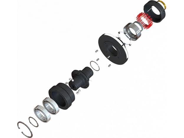
The SUNTES TY torque-releaser family disconnects torque transmission when the drive load exceeds its selected setting. The A, D and AR configurations share the same basic clutch mechanism. The A-type assembly is used here to explain how the normal transmitting state, overload release and reset sequence differ.
Normal torque transmission
Steel balls held by the hub boss are pressed into flange pockets by spring force. Torque passes from the hub boss through the balls to the flange. The bearing, case, segments, taper ring and slide ring form part of the assembly that controls its released and reset states.
Overload release and detection
When an overload pushes the balls out of the flange pockets, torque transmission is interrupted. The segments move along the hub-boss ramps against spring force and spread the case and taper ring. At the top of the hub projections, the force pressing the balls into the flange pockets is removed, allowing the flange to rotate freely on its bearing. The case moves axially toward the adjust ring, providing displacement that can be detected by a limit switch or proximity switch.
Manual reset after clearing the overload
First remove the cause of overload. Rotate either the input or output until the alignment marks on the hub boss and flange coincide. Press the case toward the flange to reset the mechanism. The released free-rotation state and deliberate reset action are essential distinctions from an automatic-reset unit. Provide access to the alignment marks and the reset mechanism in the machine layout.
Configuration and control review
Select the physical configuration to match the mounting interface and driven equipment, then use its own specification tables for the release-torque range, spring arrangement, speed and shaft dimensions. The operating diagrams explain the mechanism rather than assigning a universal rating to every size. For ordering or service discussions, identify the full model, setting, shaft arrangement, overload detector and required restart sequence. Use the component-reference drawing to identify parts accurately and confirm the current operating instructions for the chosen assembly.


Confirm the latest dimensional drawing and specifications for the selected configuration before manufacture or installation.