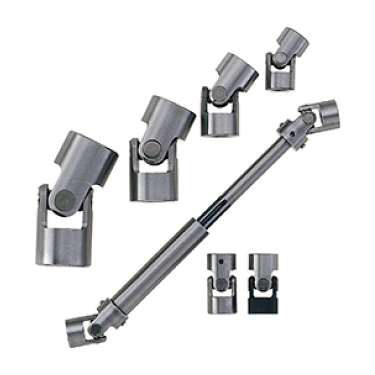
KYOWA designs the miniature cross-bearing F series for relatively high rotational speed and operation without routine relubrication of the joint. Typical applications include roller conveyors, printing machinery and equipment drives. FP adds an intermediate sliding spline.
Selection and application
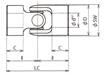
The FJ table lists the catalog limits by size, and the bearing inputs support the catalog life estimate. Review speed, torque and operating angle together. Match the FP stroke and fitted length to the machine envelope. Use the drawing symbols to check shaft connection and rotating clearance.
Catalog configurations
| Type | End and shaft options |
|---|---|
| FJ | 00A, 09A quick-change, 03A and 33A newer JIS key. Confirm size availability. |
| FP | 00A, 03A, 33A, 39A and 99A; check the selected end combination. |
FJ selection ratings
| Model | Allowable speed (rpm) | Allowable angle (°) | Allowable torque (N·m) | Static failure torque (N·m) | GD² (kg·cm²) | Mass (g) |
|---|---|---|---|---|---|---|
| FJ-32 | 5,000 | 25 | 29 | 110 | 1.5 | 250 |
| FJ-42 | 5,000 | 25 | 78 | 310 | 5.2 | 600 |
| FJ-52 | 5,000 | 25 | 140 | 580 | 18 | 1,100 |
| FJ-59 | 5,000 | 25 | 240 | 960 | 40 | 1,500 |
| FJ-70 | 3,500 | 25 | 340 | 1,300 | 77 | 2,700 |
FJ bearing calculation data
| Model | C(N) | l(mm) |
|---|---|---|
| FJ-32 | 2,700 | 22.15 |
| FJ-42 | 3,200 | 29.3 |
| FJ-52 | 5,600 | 35.3 |
| FJ-59 | 6,400 | 41.4 |
| FJ-70 | 7,000 | 47.5 |
FJ dimensions and limits (linear values in mm)
| Model | d | D | LC | l | C | E | b | t | M | EQ | I | R | JQ | bQ | tQ | Rotating diameter SW |
|---|---|---|---|---|---|---|---|---|---|---|---|---|---|---|---|---|
| FJ-32-**A | 16 | 32 | 65 | 32.5 | 18 | 9 | 5 | 18.3 | 6 | 8 | 13.3 | 3.2 | 10 | 5 | 18 | 33 |
| FJ-42-**A | 20 | 42 | 86 | 43 | 23 | 11 | 6 | 22.8 | 8 | 8 | 18.3 | 3.2 | 15 | 5 | 23.1 | 43 |
| FJ-52-**A | 25 | 52 | 108 | 54 | 30 | 14 | 8 | 28.3 | 8 | 10 | 22.53 | 4.4 | 20 | 7 | 28 | 53 |
| FJ-59-**A | 30 | 59 | 140 | 70 | 40 | 20 | 8 | 33.3 | 8 | 11 | 26.95 | 4.8 | 29 | 7 | 33 | 61 |
| FJ-70-**A | 40 | 70 | 160 | 80 | 45 | 22 | 12 | 43.3 | 12 | 12 | 37.36 | 5.2 | 33 | 10 | 43.4 | 70 |
FP dimensions and limits (linear values in mm)
| Model | d | L | Axial travel | A | B | Spline specification S | E | LC | D | F | G | H | J |
|---|---|---|---|---|---|---|---|---|---|---|---|---|---|
| FP-32-**A | 16 | 290 | +37 -21 | 225 | 117 | Involute spline Major dia.=17 m=1.0 z=15 | 30 | 65 | 26 | 21 | 67 | 110 | 50 |
| FP-42-**A | 20 | 340 | +34 -26 | 254 | 117 | Involute spline Major dia.=20 m=1.0 z=18 | 40 | 86 | 30 | 26 | 74 | 125 | 43 |
| FP-52-**A | 25 | 400 | +16 -34 | 292 | 120 | Involute spline Major dia.=25 m=1.25 z=18 | 50 | 108 | 40 | 34 | 61 | 125 | 59 |
| FP-59-**A | 30 | 495 | +20 -45 | 355 | 135 | Involute spline Major dia.=30 m=1.667 z=16 | 50 | 140 | 44 | 45 | 70 | 150 | 65 |
| FP-70-**A | 40 | 570 | +20 -50 | 410 | 155 | Involute spline Major dia.=40 m=1.667 z=22 | 60 | 160 | 60 | 50 | 80 | 175 | 75 |
Product images and drawings